Volume Rendering
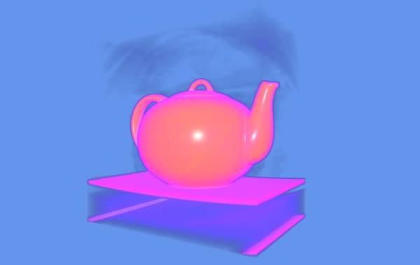
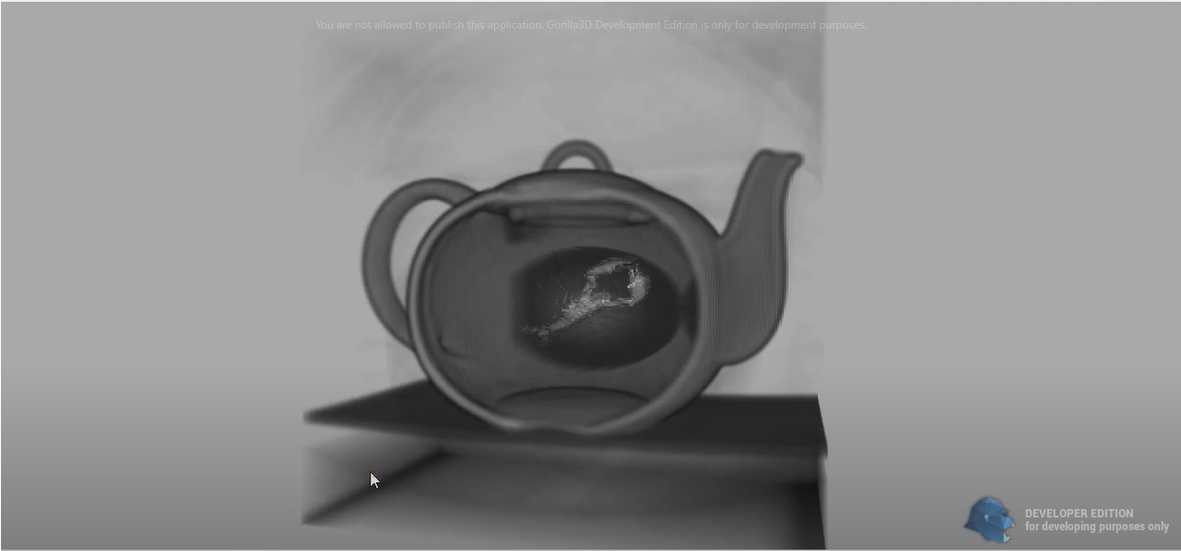
Since v0.8.3 our framework provides the TGorillaVolumetricMesh component, which allows to render 3D array data like CT or MRT scans.
This component is indispensable for medical or for security checkpoint software.
Users push their 3D data from file or stream into a Texture3D and it renders by raymarching algorithm.
Features
- Different 3D texture data sizes: UInt8, UInt16, HalfFloat, Float
- Different 3D data sizes: 4, 8, 16, 32, 64, 128, 256, 512, 768, 1024
- Allowing custom sizes
- Different render shapes: cube, sphere, cylinder
- Changable ray front and back limit
- Managable ray step detail
- Clipping plane support for optimal slicing
- RAW file support
- NRRD file support with automatic 3D data size detection
Settings
When setting volume data properties like “DataType” or “Sizes” it's recommended to encapsulate those operations in an update context, to prevent multiple texture creation.
FVolume.BeginUpdate();
try
   ...
finally
  FVolume.EndUpdate();
end;
DataType
| Value | Description | Number Of Bytes |
|---|---|---|
| TGorillaVolumetricMeshDataType.vmdtUInt8 | Unsigned Byte | 1 Byte |
| TGorillaVolumetricMeshDataType.vmdtUInt16 | Unsigned ShortInt | 2 Bytes |
| TGorillaVolumetricMeshDataType.vmdtHalfFloat | Half floating point value | 2 Bytes |
| TGorillaVolumetricMeshDataType.vmdtFloat | Floating point value | 4 Bytes |
Sizes
| Value | Description | UInt8 | UInt16 | HalfFloat | Float |
|---|---|---|---|---|---|
| TGorillaVolumetricMeshSize.vms4x4x4 | Sets up a 4 x 4 x 4 voxel 3D texture with the defined data type. | 64 Bytes | 128 Bytes | 128 Bytes | 256 Bytes |
| TGorillaVolumetricMeshSize.vms8x8x8 | Sets up a 8 x 8 x 8 voxel 3D texture with the defined data type. | 512 Bytes | 1 KB | 1 KB | 2 KB |
| TGorillaVolumetricMeshSize.vms16x16x16 | Sets up a 16 x 16 x 16 voxel 3D texture with the defined data type. | 4 KB | 8 KB | 8 KB | 16 KB |
| TGorillaVolumetricMeshSize.vms32x32x32 | Sets up a 32 x 32 x 32 voxel 3D texture with the defined data type. | 32 KB | 64 KB | 64 KB | 128 KB |
| TGorillaVolumetricMeshSize.vms64x64x64 | Sets up a 64 x 64 x 64 voxel 3D texture with the defined data type. | 256 KB | 512 KB | 512 KB | 1 MB |
| TGorillaVolumetricMeshSize.vms128x128x128 | Sets up a 128 x 128 x 128 voxel 3D texture with the defined data type. | 2 MB | 4 MB | 4 MB | 8 MB |
| TGorillaVolumetricMeshSize.vms256x256x256 | Sets up a 256 x 256 x 256 voxel 3D texture with the defined data type. | 16 MB | 32 MB | 32 MB | 64 MB |
| TGorillaVolumetricMeshSize.vms512x512x512 | Sets up a 512 x 512 x 512 voxel 3D texture with the defined data type. | 128 MB | 256 MB | 256 MB | 512 MB |
| TGorillaVolumetricMeshSize.vms768x768x768 | Sets up a 768 x 768 x 768 voxel 3D texture with the defined data type. It's an irregular size but very common for medical CT scans. | 432 MB | 864 MB | 864 MB | 1.728 GB |
| TGorillaVolumetricMeshSize.vms1024x1024x1024 | Sets up a 1024 x 1024 x 1024 voxel 3D texture with the defined data type. | 1GB | 2GB | 2GB | 4GB |
| TGorillaVolumetricMeshSize.vmsCustom | Allows to set individual slice sizes and mesh depth. But you need to take care of unsupported sizes in GPU. It may cause GPU exceptions if your graphics card do not support the size. | - | - | - | - |
KB - KiloBytes | MB - MegaBytes | GB - GigaBytes
You need to be careful with imported 3D data. As you can see in the table above, data size increases fastly by size and used datatype. It's absolutely not recommended to use huge data size like 1024 x 1024 x 1024 with float values, because most GPU's are not able to handle those texture sizes.
Custom Size
It's allowed to configure custom 3D data size. To enable this mode you need to set “Sizes” property to “TGorillaVolumetricMeshSize.vmsCustom”. You can then set CustomWidth, CustomHeight and CustomDepth. The property will automatically adjust sizes to a multiple of 2, as recommended by OpenGLES documentation.
  FVolume.BeginUpdate();
  try
    FVolume.Sizes := TGorillaVolumetricMeshSize.vmsCustom;
    FVolume.CustomWidth := 512;
    FVolume.CustomHeight := 512;
    FVolume.CustomDepth := 230; // will automatically modify to a depth of 256
    FVolume.DataType := TGorillaVolumetricMeshDataType.vmdtUInt8;
  finally
    FVolume.EndUpdate();
  end;
Or you can your values explicitly without alignment. But take care with sizes. Not all GPU's support irregular or unequal sizes.
In case you set an unsupported size, the texture creation will fail and raise an exception.
  FVolume.BeginUpdate();
  try
    FVolume.Sizes := TGorillaVolumetricMeshSize.vmsCustom;
    FVolume.CustomSize := Size3D(500, 500, 230); // will keep those sizes!
    FVolume.DataType := TGorillaVolumetricMeshDataType.vmdtUInt8;
  finally
    FVolume.EndUpdate();
  end;
Shapes
Not always is cubic rendering the best projection for volumes. Therefore we provide different mesh shapes.
| Shape | Description |
|---|---|
| TGorillaVolumetricMeshShape.vmsCube | Will set up a static cube mesh. |
| TGorillaVolumetricMeshShape.vmsSphere | Will set up a static spheremesh. |
| TGorillaVolumetricMeshShape.vmsCylinder | Will set up a static cylinder mesh. |
Details
TGorillaVolumetricMesh provides a “Details” property, which allows users to control raymarching algorithm.
The details value increases or decreases ray steps when marching through the 3D volume data.
This will have direct effect on the number of rendered slices and also on the produced color.
Sometimes its necessary to have more performance, so lower detail may be a solution.
RayLimits
Besides “Slicing” technique users can also manipulate ray cast offsets. By reducing or increasing the so called “RayLimits”.
This is an optimization to reduce marching algorithm in shader and can improve efficiency.
NOTICE: But carefully, if setting limits to low or to high it may cause slicing in view direction.
Upload Data
TGorillaVolumetricMesh provides two file formats.
- RAW File
- NRRD File
RAW File
When uploading 3D data to the volumetric mesh, you can use the direct RAW data upload method.
Here you need a file which data will be uploaded 1:1 and needs to correspond to the supplied parameters. You need to define the correct width, height, slices-count and datatype to the “LoadFromRawFile” method.
If the parameters are equal to TGorillaVolumetricMesh settings, the data will pushed directly.
In case TGorillaVolumetricMesh settings are different, the upload routine tries to cut out the relevant data.
FVolume.LoadFromRawFile('brain.raw',
    512, 512, 230, TGorillaVolumetricMeshDataType.vmdtUInt8);
NRRD File
When uploading 3D from a NRRD file, you don't need further parameters. The method will automatically read the file header and detects sizes and datatype.
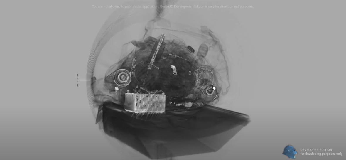
FVolume.LoadFromNRRDFile('backpack.nrrd');
You can setup a NRRD header yourself in case you have only a RAW file. Just add some similar code at the beginning of your file:
NRRD0001
content: "My NRRD File"
type: unsigned char
dimension: 3
sizes: 256 256 256
spacings: 1 1 1
encoding: raw

[... RAW DATA ...]
NOTICE: LF and CRLF are supported as line endings.
Image Slices
The component is able to load 3D data from a number of image slices, often given by medical services.
procedure LoadFromImageSlices(APath : String; const AFileNamePattern : String;
        const AFromIdx, AToIdx : Integer; const APadLeftLen : Integer;
        const APadChar : Char; const AWidth, AHeight, ADepth : Integer);
Here is an example to load such data at runtime.
- Image slices are given as *.jpg files from “IS05_001.jpg” up to “IS05_212.jpg”
- Each slice has the same size of 128 x 128 pixels
- The size of the volumetric mesh should be capable to hold this size of data, here 128 x 128
- The depth should be equal or larger than the number of slices imported, here: 212 slices and a depth of 256.
  GorillaVolumetricMesh1.RenderInside := true;

  GorillaVolumetricMesh1.BeginUpdate();
  try
    GorillaVolumetricMesh1.CustomSize := Size3D(128, 128, 256);
    GorillaVolumetricMesh1.Sizes := TGorillaVolumetricMeshSize.vmsCustom;
    GorillaVolumetricMesh1.DataType := TGorillaVolumetricMeshDataType.vmdtRGBAUInt8;
    GorillaVolumetricMesh1.Details := 0.1;
  finally
    GorillaVolumetricMesh1.EndUpdate();
  end;

  GorillaVolumetricMesh1.LoadFromImageSlices(
    '.\DICOM\P0000001\S0000001\', 'IS05_%s.jpg', 1, 212, 3, '0', 128, 128, 212
    );
The method expects the following input arguments for dynamic filename masking:
| Argument | Type | Value |
|---|---|---|
| APath | String | Directory where all images are |
| AFileNamePattern | String | A pattern for dynamic filename masking |
| AFromIdx | Integer | Index of first slice |
| AToIdx | Integer | Index of last slice |
| APadLeftLen | Integer | Length of left padding |
| APadChar | Char | Character for left padding |
| AWidth | Integer | Width of the image data |
| AHeight | Integer | Height of the image data |
| ADepth | Integer | Depth of image image data / Number of slices |
Procedural Data
You can of course fill the 3D data array also manually. Pushing data to the 3D-texture by UpdateBuffer() expects to fill data correctly. Otherwise exception may occur.
You have to take care of the 3D-texture size by the “Sizes” property of the component and the configured “DataType”.
In the following a simple code snippet showing a procedure to fill a 512 x 512 x 512 with 4-Byte float values.
uses Gorilla.Material.Types, Gorilla.Context.Texturing;

TMyVolumetricMesh = class(TGorillaVolumetricMesh)
  procedure RandomFill();
end;

{...}

procedure TMyVolumetricMesh.RandomFill();
var LTex    : TGorillaTextureBitmap;
    LData   : TBytes;
    LDPtr   : PSingle; // vmdtFloat !!!
    LValue  : Byte;
    LOfs,
    w, h, d : Integer;
    LSizeF  : TPoint3D;
    LSizeI  : record
                X : Integer;
                Y : Integer;
                Z : Integer;
              end;
    LFSize,
    LDSize  : Integer;
begin
  Self.Sizes := TGorillaVolumetricMeshSize.vms512x512x512;
  Self.DataType := vmdtFloat; /// !!!

  // get size in fragments
  LSizeF := Self.GetSizeAsVector();
  LSizeI.X := Round(LSizeF.X);
  LSizeI.Y := Round(LSizeF.Y);
  LSizeI.Z := Round(LSizeF.Z);

  LFSize := GORILLA_VOLUMETRIC_MESH_DATASIZE[Self.DataType];

  // create data array
  LDSize := LSizeI.X * LSizeI.Y * LSizeI.Z * LFSize;
  System.SetLength(LData, LDSize);
  try
    LDPtr := @LData[0];
    // fill data with perlin noise
    for w := 0 to (LSizeI.X - 1) do
    begin
      for h := 0 to (LSizeI.Y - 1) do
      begin
        for d := 0 to (LSizeI.Z - 1) do
        begin
          // NOTICE: MAYBE THE VALUE NEED TO BE IN REVERSED BYTE ORDER!
          LDPtr^ := Single(RandomRange(0, 10000) / 10000);
          Inc(LDPtr);
      end;
    end;

    // push data to 3D texture
    LTex := TGorillaVolumetricMeshMaterialSource(FMaterial).Texture as TGorillaTextureBitmap;
    LTex.UpdateBuffer(LData, LDSize);
  finally
    System.SetLength(LData, 0);
  end;
end;
Scene Setup
Volume Rendering consists of multiple steps or rather pre render-passes. Those compute front and back vertex positions of the current view. This optimizes raymarching algorithm in the final volume rendering.
Gorilla3D already contains both render passes, which only need to be setup and linked to the volumetric mesh.
uses
  Gorilla.Volumetric.Mesh,
  Gorilla.Controller.Passes.Face;

[...]

  // a pre render-pass to get all vertex positions of front faces
  FFrontFaceRenderPass := TGorillaRenderPassFace.Create(GorillaViewport1, 'FrontFace');
  FFrontFaceRenderPass.FaceKind := TFaceKind.FrontFace;
  FFrontFaceRenderPass.Viewport := GorillaViewport1;

  // a pre render-pass to get all vertex positions of back faces
  FBackFaceRenderPass := TGorillaRenderPassFace.Create(GorillaViewport1, 'BackFace');
  FBackFaceRenderPass.FaceKind := TFaceKind.BackFace;
  FBackFaceRenderPass.Viewport := GorillaViewport1;

  // create the volume mesh
  FVolume := TGorillaVolumetricMesh.Create(GorillaViewport1);
  FVolume.Parent := GorillaViewport1;

  // link pre render-passes
  FVolume.FrontFaceRenderPass := FFrontFaceRenderPass;
  FVolume.BackFaceRenderPass  := FBackFaceRenderPass;

  // only the volume itself should be rendered for front/back face detected
  // this will ignore all other objects.
  FFrontFaceRenderPass.AllowControl(FVolume);
  FFrontFaceRenderPass.Enabled := true;
  FBackFaceRenderPass.AllowControl(FVolume);
  FBackFaceRenderPass.Enabled := true;

  // configure some settings
  FVolume.Details := 0.5; // lower ray detail - default is 1.0
  FVolume.SetSize(4, 4, 4);

  // change from cube to sphere projection
  FVolume.Shape := TGorillaVolumetricMeshShape.vmsSphere;
Slicing
A great feature many applications will need with volume rendering is so called “Slicing”.
It will clip specific parts of the computed mesh, so you can have a closer look on each slice of the rendered data.
It works by a clipping plane with a direction/normal vector and a distance to the mesh origin. To modify the clipping plane is quite easy:
uses Gorilla.Context.Types;

[...]
var LDistance : Single;
    LNormal : TPoint3D;

  // get the clipping plane normal
  case AMode of
    1 : begin
          // back
          LNormal := TPoint3D.Create(0, 0, -1);
        end;

    2 : begin
          // top
          LNormal := TPoint3D.Create(0, 1, 0);
        end;

    3 : begin
          // bottom
          LNormal := TPoint3D.Create(0, -1, 0);
        end;

    else
      begin
        // front
        LNormal := TPoint3D.Create(0, 0, 1);
      end;
  end;

  // get the distance of the clipping plane to mesh origin
  LDistance := TrackBar1.Value / 100;

  // finally set the clipping plane
  FVolume.ClippingPlane := TPlaneF.Create(LNormal.X, LNormal.Y, LNormal.Z, LDistance);

  // rerender viewport to visualize changes
  GorillaViewport1.Invalidate();
Gamut Mapping
Gamut is a colored texture to define how 3D values will be colored. Since 0.8.3.2265 this feature is available.
Here an example of a simple gradient gamut texture:

TGorillaVolumetricMesh allows to configure the coloring method by some properties:
| Property | Description |
|---|---|
| Gamut | Texture used for mapping the 3D value during Raytracing |
| GamutMode | Defines when and how the value-color mapping happens. Here different modes are available: GamutNone, GamutByValue, GamutByValueMultiply, GamutBySum, GamutBySumMultiply |
| GamutFactor | A factor applied to the absolute 3D value before mapping onto the gamut texture (default value is 1.0). Use this value for shifting inside of the gamut texture. |
| GamutIntensity | Defines how intense coloring is. |
| GamutAlphaIntensity | Defines how intense alpha channel coloring is. |
Modes
The available gamut modes allow to control the output of color mapping.
| Mode | Description |
|---|---|
| GamutNone | Gamut mapping is disabled |
| GamutByValue | Gamut mapping will be applied to each 3D value on the casted ray. |
| GamutByValueMultiply | Gamut mapping will be applied to each 3D value on the casted ray and afterwards multiplied with the previously computed color value. |
| GamutBySum | Gamut mapping will be applied to the final casted ray value. |
| GamutBySumMultiply | Gamut mapping will be applied to the final casted ray value and afterwards multiplied with the previously computed color value. |
Lighting
Since v0.8.4.2314 lighting and iso surface detection is also supported.
To activate lighting for a volumetric mesh, please use:
GorillaVolumetricMesh1.UseLighting := true;
After it was activated, the implemented functions try to detect a surface from the given 3D data. This is called IsoSurface detection.
Because this method always depends on the data, you can control this detection by IsoSurfaceLimit property.

GorillaVolumetricMesh1.IsoSurfaceLimit := 0.125;
When detection of a volume surface was successful, we are able to apply lighting with all available shading models to it.
The volumetric mesh therefore allows to choose between: Lambert, Phong, Blinn-Phong and PBR.

GorillaVolumetricMesh1.ShadingModel := TGorillaShadingModel.smPBR;
Notice: For PBR (physically based rendering) it does not need any PBR texture, instead it will use the AOBias, RoughnessBias and MetallicBias properties.
Filtering and MipMaps
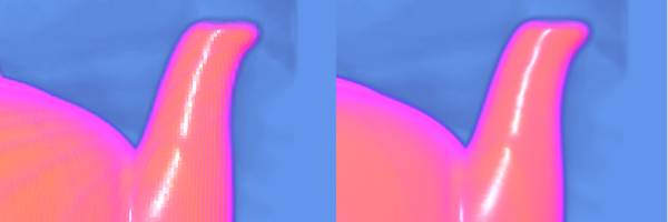
Since v0.8.4.2314 switching between nearest and linear filtering is supported. You are also able to activate MipMaps, but in most test cases the result was unsatisfying.

The picture above is showing difference between nearest (left) and linear (right) filtering. In most cases linear filtering is the expected output, but for some customers exact display of 3D data values is necessary.
GorillaVolumetricMesh1.LinearFiltering := true;
GorillaVolumetricMesh1.MipMaps := false;
Multiple VolumetricMeshes / Complex Scenes
In case you're intending to place multiple instances of a volumetric mesh in your scene OR other objects intersecting / overlapping the volumetric mesh, you have to be aware of the internal functionality.
The needed render passes for front-face and back-face detection are only useful for a single volumetric mesh.
Placing multiple intersecting / overlapping objects in your scene may lead to unexpected results.
Front- and back-face detection is needed by internal raytracing algorithm to define the start and the end of a specific volume. So this render passes need to render exactly this specific volume and nothing else above or behind!
When having multiple instances those values can overwrite each other and lead to intersection problems.
Therefor you need to setup Front- and back-face render passes for each volumetric mesh.
/// SETUP VOLUME #1 RENDER PASSES
FFrontFaceRenderPass1 := TGorillaRenderPassFace.Create(GorillaViewport1, 'FrontFace1'); // !!! unique ID
FFrontFaceRenderPass1.FaceKind := TFaceKind.FrontFace;
FFrontFaceRenderPass1.Viewport := GorillaViewport1;

// exclude all other volumetric meshes or other objects - that the render pass only renders the relevant volume
FFrontFaceRenderPass1.AllowControl(FVolume1); // !!! only compute Volume #1
FFrontFaceRenderPass1.Enabled := true;

FBackFaceRenderPass1 := TGorillaRenderPassFace.Create(GorillaViewport1, 'BackFace1'); // !!! unique ID
FBackFaceRenderPass1.FaceKind := TFaceKind.BackFace;
FBackFaceRenderPass1.Viewport := GorillaViewport1;

// exclude all other volumetric meshes or other objects - that the render pass only renders the relevant volume
FBackFaceRenderPass1.AllowControl(FVolume1); // !!! only compute Volume #1
FBackFaceRenderPass1.Enabled := true;

FVolume1.FrontFaceRenderPass := FFrontFaceRenderPass1;
FVolume1.BackFaceRenderPass := FBackFaceRenderPass1;


/// SETUP VOLUME #2 RENDER PASSES
FFrontFaceRenderPass2 := TGorillaRenderPassFace.Create(GorillaViewport1, 'FrontFace2'); // !!! unique ID
FFrontFaceRenderPass2.FaceKind := TFaceKind.FrontFace;
FFrontFaceRenderPass2.Viewport := GorillaViewport1;

// exclude all other volumetric meshes or other objects - that the render pass only renders the relevant volume
FFrontFaceRenderPass2.AllowControl(FVolume2); // !!! only compute Volume #2
FFrontFaceRenderPass2.Enabled := true;

// a pre render-pass to get all vertex positions of back faces
FBackFaceRenderPass2 := TGorillaRenderPassFace.Create(GorillaViewport1, 'BackFace2'); // !!! unique ID
FBackFaceRenderPass2.FaceKind := TFaceKind.BackFace;
FBackFaceRenderPass2.Viewport := GorillaViewport1;

// exclude all other volumetric meshes or other objects - that the render pass only renders the relevant volume
FBackFaceRenderPass2.AllowControl(FVolume2); // !!! only compute Volume #2
FBackFaceRenderPass2.Enabled := true;

FVolume2.FrontFaceRenderPass := FFrontFaceRenderPass2;
FVolume2.BackFaceRenderPass := FBackFaceRenderPass2;
Next step: Particles

